Technology Exposé:
Parametric Rule Editor (PRE)
Flexible pattern search and full-chip pattern segmentation are becoming increasingly important tools for effective yield learning and yield enhancement.
Flexible Pattern Search
A typical physical layout (GDS/OASIS) consists of patterns and subtle to substantial variations of the patterns. Often it is necessary to search for a pattern while specifying precise constraints for finding variations of the pattern in a controlled, deterministic way.
Full-Chip Pattern Segmentation
Advanced inline inspection tools from the leading vendors have provided array mode inspection and random mode inspection. Array mode inspection significantly enhances sensitivity to defects in memory arrays. Because noise characteristics within an array are fairly uniform throughout the array, the threshold setting can be lowered compared with the threshold in random logic regions. However, even random logic regions can be segmented on the basis of uniform pattern characteristics such as line orientation, line density, pattern complexity, and so on, to generate micro care areas. Segmenting the logic regions into homogeneous subregions allows each subregion to be thresholded individually for best sensitivity and noise rejection.
Anchor’s Parametric Rule Editor (PRE) provides an elegant and user-friendly solution for both of these applications. It is a groundbreaking product that provides supreme flexibility with unmatched ease-of-use.
PRE can be used to build simple or complex search rules on patterns that are either imported from a file or drawn by hand using polygon-editing functions built right into the product. Exact constraints for a number of geometric properties such as line width and line space can be specified, with full support for multiple layers.
Want to check if there is a single-via of a specified width with specified coverage within a specified distance from the end of line that is of a specified width and has a minimum specified run length? No problem. This example combines a via layer and an interconnect layer, yet it is a relatively simple example of the flexibility offered by PRE.
In this section we walk through a sample use case to demonstrate some of the capabilities of the Parametric Rule Editor.
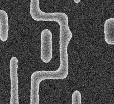
The Physical Failure Analysis (PFA), Diagnostics, or Yield Enhancement group just handed you a SEM image of a potential weak pattern. You suspect the small metal island that is surrounded by pattern on three sides. You decide to search for this pattern on the full chip, but you pause for a moment to consider the following:
1. It would be more meaningful if there was a via connecting this metal island. You want to avoid ‘floating metal’ that is of no consequence.
2. You feel that there might be several variations of this pattern that might be quite relevant. You decide that this pattern and its variants are ‘Patterns of Interest’ or POI that should be searched.
Although we can use Image Explorer’s contour extraction feature to lift this pattern out of the SEM image, we note that the pattern is simple enough to be drawn manually within the PRE GUI. We don’t need an exact rendering because we will specify numeric constraints.
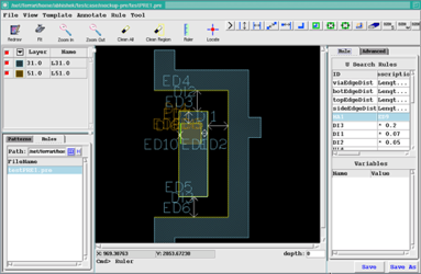
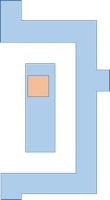
Within a few seconds we use the PRE GUI to draw the pattern on the right.
Within a few seconds we use the PRE GUI to draw the pattern on the right.

Because we want to ensure that the metal island contains a via (otherwise it would be a ‘floating metal’ or dummy structure), we also draw a via.
Now the base pattern is complete and we move on to specifying the necessary constraints.
Now the base pattern is complete and we move on to specifying the necessary constraints.
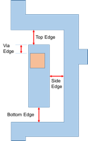
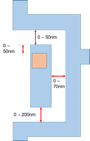
The process of defining constraints begins with identifying the key geometric properties. In this case we want to ensure that the metal island is flanked on three sides, that it contains a via, and that the via is located within a specified distance from the line end.
This can be achieved by examining the 4 properties illustrated on the right.
This can be achieved by examining the 4 properties illustrated on the right.
The parametric pattern search engine applies the user’s constraints on the entire die or any subarea. The results can be viewed in several ways. A common view is the Tile View that shows all of the unique patterns that were found and allows the user to iterate through each of the instances of those patterns across the die.
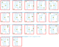
On the left we can see 17 variations of the pattern. Each of the 17 variations may have hundreds or thousands of instances. Note the subtle variations in each of these 17 patterns. Note also the variation in the location of the via.
On the left we can see 17 variations of the pattern. Each of the 17 variations may have hundreds or thousands of instances. Note the subtle variations in each of these 17 patterns. Note also the variation in the location of the via.
Because we defined variables to track top edge distance, side edge distance, bottom edge distance, and via edge distance, we can view the distribution of values for each of these variables.
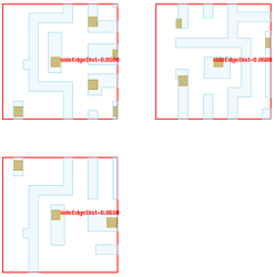
For example, the gallery on the left shows the 3 different values of side edge distance that were found. These values (0.05um, 0.06um, and 0.065um) can be plotted on a histogram to show how many instances had a side distance of 0.05um, how many had a distance of 0.06um, etc. Filtering and sampling operations are also provided to narrow down the population into one or more subsets.
For example, the gallery on the left shows the 3 different values of side edge distance that were found. These values (0.05um, 0.06um, and 0.065um) can be plotted on a histogram to show how many instances had a side distance of 0.05um, how many had a distance of 0.06um, etc. Filtering and sampling operations are also provided to narrow down the population into one or more subsets.
